Informational Documents
Plastics Technology Magazine
| INJECTION MOLDING: Gate Freeze Study: Danger in a Name? |
Plastics Today
| A colder injection mold doesn’t always result in colder part temperatures |
Injection Molding Magazine Articles
Asian Plastics News Articles
MoldMaking Technology Articles
Tooling Product News Articles
| The Evolution of Today’s Mold Builder (By Rod Groleau & Patricia Hirst, RJG Inc.) |
Medical
| Revalidation Using Machine Independent Data |
Ready-To-Go Molds with Cavity Pressure part 1 of 2
You are a good molder. You can make any reasonable mold produce good parts. It may take a little time to tweak them in, but you do well most of the time.
Your customers are constantly beating you up when you send them any bad parts. They expect absolute quality and price concessions at the same time! In addition to these challenges, your competition is ruthless. So you just don’t know what else to do.
That scenario is all too familiar. Many molders understand how to tweak processes and have mastered all of the tricks of the trade but it’s not enough in today’s world. Today you need to know and think like your customers.
Customers for molded parts are under tremendous strain today. They have to deliver absolute quality parts; with shorter lead times and shrinking margins and what they need from you is a quick response and 100% good parts. Sound impossible? It isn’t if you start with a Ready-To-Go mold.
A Ready-To-Go mold can be defined as a mold that can be put in the press, set up by the least qualified molding technician, without breaking any rules. It can make parts predictably and quickly on cycle and can run unattended without adjustment throughout the run.
How do you get a Ready-To-Go mold? In this two part series, all the details of Ready-To-Go molds will be discussed, from verifying fit and function in part 1, through process development in part 2.
Part 1- Fit and Function
You must start with a good design of both the part and mold with no broken rules. Obviously, it is also important that the mold be built to exacting standards and thoroughly tested to insure all items function as designed.
Always pre-flight the mold
Many important features of the mold should be checked before it is ever clamped into a molding machine. Coolant flow and pressure loss through the cooling channels should be quantified before sending the tool on to the molding room. Any moving cores or slides should be checked for freedom of movement with the mold pre-heated to the desired operating temperature. Also, if there is a hot manifold it should be carefully checked for any potential problems prior to scheduling a tool try-out in a production machine.
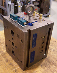
Figure 1.
Once the basics are verified it is time to perform a ‘Rigorous Mold Try Out’.The objective of a Rigorous Mold Try Out is simple: Challenge the mold early and hard to avoid problems once the mold goes into production. It sounds almost too obvious to mention, but many molders fail to perform this important phase of mold development. The reasons are all too familiar: “There will be time to fix the mold after the customer approves the parts – we can’t afford to miss this deadline!” The costs of rushing to market without robust tooling can be measured in more than just the immediate bottom line profits. It can degrade your reputation resulting in lost opportunities for future business – sometimes ending in severed customer relationships.
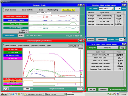
Figure 2.
The tryout
A Rigorous Mold Try Out starts with following the directions from the material manufacturer. The barrel, nozzle, (and when applicable – hot manifold) temperatures should be set to deliver plastic at a melt temperature in the middle of the recommended range. Next, the mold must be filled as fast as consistently possible. There should be no jetting, burning, or flash when the mold is filled fast.
DECOUPLED MOLDINGSM is a technique that separates the fast filling of the mold from the sudden stop when the end of cavity is reached. This technique should be used during all new mold tryouts to insure that the mold is capable of running a robust process during production. At this time, it is also crucial to measure the degree of balance between the various cavities on a multi-cavity mold.
After filling, the mold must be pressurized to get a good imprint of the cavity and minimize the effects of volumetric shrinkage. It is important that any new mold be packed to a minimum pressure of 3000psi or 200mpa at the end of the cavity. Any mold that cannot be pressurized to this degree at the last area to fill without flash will most likely be problematic when normal viscosity variations of material occur during production runs.
As part of a Rigorous Mold Try Out, we at RJG believe it is essential to instrument the mold with cavity pressure sensors to see what is going on inside the mold. The sensor(s) allow you to quantify if the mold can be packed properly without adverse effects. It is also important to determine whether or not the gate is sealed after the cavity has been pressurized. Observing cavity pressure near the gate and seeing whether or not it is maintained after hold pressure is removed, is the simplest most effective way to determine gate seal.
Since cooling is approximately 80% of the cycle, challenging the mold cooling system before a mold goes into production is crucial. Proper flow through each cooling channel should be verified before the mold ever leaves the tool room. During the Rigorous Mold Try-out it is important to create a mold surface temperature map. Cavity pressure data can greatly assist in repeating cooling conditions in production runs as any changes to cooling will be evidenced by changes in the cavity pressure drop off.
Any problems uncovered during the Rigorous Mold Try-out should be corrected before continuing. If any good parts are molded before the mold is corrected they should be destroyed. Too many times the excuse of “it made good parts last time it ran” has been used to keep poor performance tools from becoming Ready-To-Go tools.
In summary, the methodology to develop and launch Ready-To-Go molds is here and proven. It requires teamwork by all involved. Education is essential. Following this advice will pay big dividends for the few who have the discipline to carry it out.
Next month, in part 2, we will continue with discussing process development and tool adjustment.
Ready-To-Go Molds with Cavity Pressure part 2 of 2
In last months article “Ready-To-Go Molds with Cavity Pressure part 1”, we defined Ready-To-Go molds as a mold that can be put in the press and set up by the least qualified molding technician without breaking any rules. It can make parts predictably and quickly on cycle and allowed to run unattended without adjustment throughout the run.
Part 1 focused on fit and function. We discussed performing a pre-flight check on the mold to uncover any concerns before processing plastic. After pre-flight, a rigorous mold tryout is performed to wring out potential mold issues that may inhibit a robust production process. To properly perform the rigorous tryout, cavity pressure sensors are essential. The sensors give the tryout team real-time data allowing them to make accurate tooling adjustments. Information related to cavity-to-cavity balance, proper packing levels, cavity fill and pack times, and gate seal are just a few examples.
Part 2 – Process development and tool adjustment
Process development involves developing a robust process and then adjusting tooling to reach consistent part quality requirements. The process will be a DECOUPLED MOLDINGSM process, which allows for separation of the filling and packing phases of the process to gain better control. Filling will be done on the machine’s first stage, not pressure limited, and will be terminated on a stroke (screw) position with the cavities 95-99% full. Packing and holding will be accomplished utilizing the machine’s second stage pressure. Cavity pressure sensors will be used only to monitor the in-cavity conditions and repeatability of those conditions initially.
Filling the Mold
With the melt temperature within the material manufacturer’s recommended range, an in-mold rheology study will be performed. The rheology curve is used to guide in fill speed selection. Rheology data does not dictate fill speed; rather it provides information related to how different shear rates affect material viscosity and also the stability of the material viscosity at various fill rates/shear rates. Ultimately, the fastest injection speed that reliably produces quality parts will be selected. After setting the fill speed, the stroke distance is then adjusted to produce “fill only” short shots that are 95-99% full at the transfer position with no pack or hold.
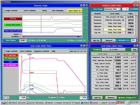
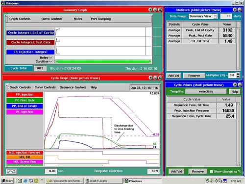
Process screen shot showing a template and a process change.
Packing the Mold
After filling, the cavities must be pressurized (packed) to minimize the effects of shrinkage during cooling. With a DECOUPLED #2 process, packing will be done using the machine’s second stage pressure. Monitoring cavity pressure, the machine’s packing pressure will be increased until a minimum pressure at the end of the cavity of 3,000psi or 200mpa is reached. Next, the machine’s hold timer is increased until the cavity pressure at the gate end of the part does not suddenly decay coincident with the end of holding time. This decay or “drop-off” in cavity pressure would indicate plastic discharging back through the gate.
Cooling
Having already checked the mold cooling system in the pre-flight stage, the cooling portion of the actual process must now be optimized. The part needs to maintain it’s desired shape and be able to withstand the forces of ejection prior to opening the mold. Achieving both of those goals within the desired cycle time can require a significant amount of experimentation, but the economic rewards are definitely worth it.
Capability Study
After development of the process, measuring true capability is the next step. The key here is to include normal variation in the study. This involves introducing a material viscosity change to the process and measuring the effect from inside the cavity. Because plastic viscosity cannot be held constant, ensuring real capability cannot be measured without accounting for normal variation. The cavity pressure sensors will illustrate actual in-cavity variations related to pressure gradient, changes in peak, time to peak, etc as viscosity variation occurs. This data is directly related to part quality characteristics such as flash, shorts, dimensional variation, strength, gloss, and part weight.
Tool Adjustments
The cavity pressure data and part quality inspection data from the capability study can now be used to make tooling adjustments. Because normal viscosity variation was introduced during the capability study, the steel can be modified based on the changes in part quality as a result of the viscosity variation. The goal is to make adjustments to the mold so that variations in viscosity during production will still render parts within specification callouts. It is one thing to produce a few acceptable parts in a controlled environment and send the mold to the production team. It is quite another to test true capability including normal process variation and then tune the mold steel so that all cavities run at the mean.
Any processor can make one good part with any mold. In order to stay competitive in today’s arena, however, molding companies need strategies to guarantee total quality from concept to production. Ready-to-go molds are an essential piece to the puzzle. Time wasted “tweaking” the process is expensive and has to be eliminated.
Process Template
Once the mold is Ready-To-Go and a robust process has been developed, the next step is to save an electronic fingerprint of the process by creating a template that includes all graphical and numerical data related to the target process. The tryout team can now send the Ready-to-go mold and the electronic template to the production facility. The production team now puts the mold in their machine and matches the cavity pressure template. This saves valuable time and paves the road to seamless production launches. The use of cavity pressure sensors allows everyone involved to make accurate decisions on what modifications need to performed, significantly reducing guess work.
If the final production process is not capable of producing quality parts long term, the next consideration would be to utilize the cavity pressure sensors for process control. In upcoming issues, we will discuss cavity pressure control and how the sensor can send signals to the molding machine based on cavity conditions to reach the highest level of process capability.
To some, having molds that are “Ready-To-Go” may seem like a concept that is unachievable. It is a methodology, however, that streamlines product launches and will ultimately decide the difference between surviving and thriving for molding companies in the future.
Cavity Pressure Control
So far in this cavity pressure series we’ve discussed the importance of cavity pressure sensing, sensor placement, proper installation, and utilizing cavity pressure data to guarantee molds are “Ready-To-Go.” Last month in “Ready-to-go Molds – Part 2”, we discussed developing a Decoupled II process and the importance of separating the filling and packing phases of the injection process to fully utilize the molding machine’s capability to produce consistent, high quality parts.
The mold is now Ready-To-Go. The machine is world class and running a Decoupled II process. Will this be enough to maintain expected quality demands long term? In a Decoupled II process, packing is done using a constant pressure supplied by the molding machine. In turn, when the material viscosity varies, the amount of plastic packed into the cavities will also vary. Even the most capable molding machine will not automatically use a higher packing pressure as plastic viscosity trends upward nor will it decrease its packing pressure as viscosity trends downward. So, a world-class machine on a steady state cycle will inevitably over or under pack parts as normal variations in plastic viscosity occur. If this scenario translates into unacceptable part quality variation, a higher level of process controls is obviously needed.
The effects of this type of normal viscosity variation can be minimized using cavity pressure sensing technology. Cavity pressure control provides an elevated level of process capability by moving the control or pivot point of the process from the tip of the screw, as it is in Decoupled II molding, to the gate end of the cavity, which will significantly reduce variation in the cavity. See Figure 1
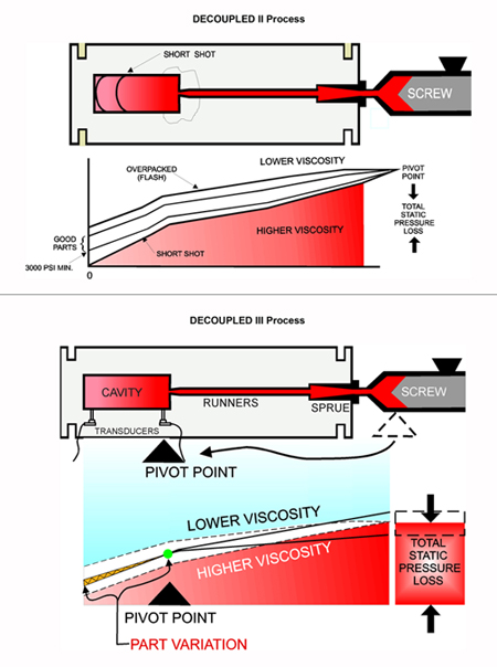
Figure 1 – Process pivot point of a DECOUPLED II vs. DECOUPLED III process
Decoupled III molding involves the use of a cavity pressure sensor located at the gate end of the cavity, to signal the molding machine when sufficient packing levels are achieved inside the cavity. First, the mold is filled under velocity control (not pressure limited) to a screw position which fills the cavity 85-90%. At this screw position, a second slower injection velocity is activated to finish filling the cavity and then to pressurize the cavity to a cavity pressure set point. This second velocity is typically 5-10% of the initial filling velocity. The essence of a Decoupled III process is to pack using a low, controlled velocity that is not pressure limited until a cavity pressure is reached. This ensures that the same pressure is reached inside the cavity, shot after shot. Once the cavity pressure sensor detects the set pressure, a signal is sent to the machine to switch into the machine’s second stage for hold. Holding pressure is now used to simply “hold” the plastic in the cavity until gate seal is achieved.
The cavity pressure sensor has exclusive control of how much plastic material is packed into the cavity. When the viscosity of the plastic varies, the desired cavity pressure will be maintained. During packing, the machine simply pushes the screw forward at the set velocity with an abundance of available pressure until the cavity pressure sensor signals the machine transfer into second stage for holding. As viscosity trends up and down, the machine will merely use more or less of its available energy to pack at a constant velocity and maintain in-cavity pressures. Consistently packing the cavities to the same pressure each cycle is paramount for controlling such part quality characteristics as flash, short shots, dimensions, knit line strength, part weight, gloss, and texture.
It is important to note that “Cavity Pressure Control” or Decoupled III molding as defined by RJG, utilizes a cavity pressure sensor to terminate the packing phase of the process, not the filling phase. A “Cavity Pressure Transfer” type of process, which is often confused with Cavity Pressure Control, involves using a cavity pressure sensor to transfer the machine from fill to pack, and then packs with a machine generated pressure (limited) as with a Decoupled II process. Pressure limiting pack, as stated earlier, leaves the packing phase of the process sensitive to viscosity variation. Simply transferring on cavity pressure is not recommended, as the viscosity of plastic will affect the volume of material in the cavity when the transfer cavity pressure is reached. This technique has proven to be even less capable than a Decoupled II process. See Figure 2
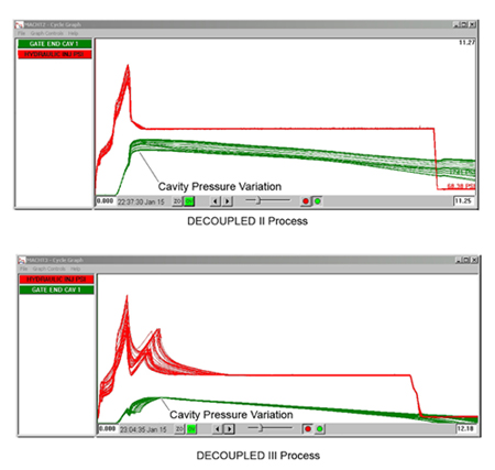
Figure 2 – DECOUPLED II vs. DECOUPLED III process variation
Decoupled III molding provides the ultimate in process control by absorbing the effects of viscosity variations. This technique is not intended to produce parts of higher quality, but rather to duplicate part quality forever. Most would agree that Decoupled III processing is the most consistent method of molding plastic parts available to molders today. However, a common concern is whether Decoupled III control is really a necessity for any particular mold. There is a simple test to determine this. Start by running a Decoupled II process and force a viscosity change on the fly. The viscosity change should be around 10%, and can typically be accomplished by running 100% virgin plastic and switching to 100% regrind plastic. If the quality of parts produced throughout this run do not fall within specifications, it’s clear that the current process is not truly “in control”. Decoupled III molding is the answer to this problem for many molds, particularly those with high pressure drops, small shot sizes (using less than 20% of the barrel), or those using engineering grade materials.
In summary, maintaining in-cavity conditions as normal process variation occurs has to be the goal of any process control strategy. A “state-of-the-art” molding environment is one piece of achieving that goal. However, the best machines, molds, etc. cannot absorb the effects of plastic viscosity variation. Cavity pressure control using Decoupled III molding puts the control inside the cavity where the critical part quality characteristics are determined. By keeping the pressure inside the cavity consistent from shot to shot, the highest levels of process capability can be achieved.
MAKE YOUR MOLDS MACHINE AND LOCATION INDEPENDENT BY UTILIZING IN-CAVITY PRESSURE DATA
Proving process capability to the customer is very time consuming and costly, and if that isn’t bad enough, customers require molders to re-prove capability each time their mold is moved to a different machine. Molders need a way to prove to customers that they can mold the same quality parts in different machines and be able to provide solid data to prove it. In-cavity sensors can help provide this data, allowing molders to save time and reduce costs.
Traditional Methods and Where They Fall Short
Traditional methods of proving capability to customers rely heavily on process and part documentation. The process documentation often includes machine set-points for temperatures, speeds, times and machine pressures. The part documentation includes extensive part measurement data from controlled production run-offs. Other information may be included, such as plans to ensure continued quality in the future, but the primary information is related to the process and the part.
The problem with this method arises when the molder needs to move the mold to an alternate machine. In today’s world of just-in-time delivery, the molder competes by shuffling jobs to alternatively capable machines as they become available. Moving molds to different machines is inevitable. If the process documentation is based on machine settings, it is logical that customers would want process capability re-verified whenever their mold is moved to a new machine.
So what’s a molder do? Take the time and expense to re-prove the capability on new machines when circumstances dictate moving the mold – or take a new approach and avoid this increased cost of quality all together?
An Effective Alternative – Use Cavity Pressure Data to Prove Capability
True process capability relies on consistent delivery of four key plastic variables inside the mold cavity: Plastic Temperature, Flow-Rate, Pressure Gradient, and Cooling Rate & Time. When these four plastics variables are matched, the same part will be created, regardless of which machine the mold is run in.
Plastic melt temperature:
The melt temperature is the temperature of the plastic as it is delivered into the mold. Barrel temperatures (whether actual measured values or set points) should never be assumed to represent the actual melt temperature. Often, the actual melt temperature can vary from the barrel temperature settings by up to 200 C. The melt temperature can also be affected by screw RPM, screw geometry, and back pressure. While in-mold temperature measurements are difficult to obtain, the effect of melt temperature can often be seen in the cavity pressure curves — hotter material takes longer to cool and depressurize inside the cavity.
Plastic flow rate:
This is the flow rate of the plastic inside the mold, not the screw speed profile itself. The actual flow rate depends on the diameter of the screw, the injection speed used, the consistency of check ring seating, and even on the size of the cushion. Flow rate can be measured directly using cavity pressure sensors. These sensors can detect the time at which melt arrived at the sensor, which is directly related to in-mold flow rate.
Plastic pressure gradient:
The pressure of the plastic inside the mold is one of the most important factors impacting part quality. Too much pressure and the part flashes – too little and the part is short or has sinks. Dimensions, texture, and part strength are also related to in-mold pressure. Unfortunately, it is difficult to determine the in-cavity pressures using only machine data. Cavity pressure data is a precise measure of the pressure inside the mold, independent of machine or location.
Plastic cooling rate / time:
The plastic cooling rate is the difference between the melt temperature and the temperature of the mold cavity steel. Like melt temperature, it is difficult to measure this directly. In-mold thermocouples can give a good indication of steel temperature inside the cavity. Cavity pressure sensors can also provide an indirect measure of cooling by monitoring the rate of depressurization in the mold.
A “template”, or in-mold snapshot of the ideal process, can be created and saved electronically capturing all of these plastic conditions at any given moment in time. A template gives the molder data-based targets, independent of machine or location, to help replicate the same plastic conditions in future molding cycles. These powerful templates are obtained through the use of in-mold cavity pressure sensors in combination with a process monitoring and control system.
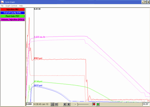
The following graphical process data illustrates how far off machine set points can be from true in-cavity conditions. Figure 1 shows a process template that has been “matched” by adjusting the machine set points as needed to create the same plastic pressure inside the mold cavity. The template was created using an electric molding machine with a toggle clamp unit. The matching process was later developed in a hydraulic molding machine of equivalent tonnage with a similar shot capacity.
Notice how much different the machine pressure and volume curves are in this captured cycle in order to duplicate the same pressures inside of the mold cavity. Imagine the difficulty in trying to make the same part without using in-cavity data. All four plastic variables would have to be matched largely by trial and error. Using in-cavity data allows the four plastic variables to be matched quickly and precisely with real data instead.
Of course the customer still requires evidence that the “matched process” has actually molded product that meets their specifications. This involves simply measuring a number of parts molded at the accepted process conditions and proving with measurement data that they consistently meet the specifications.
Using the cavity pressure templates as machine independent verification that the process conditions are met, in combination with part measurement data that proves the customer specifications are met statistically, is the ultimate means of proving capability.
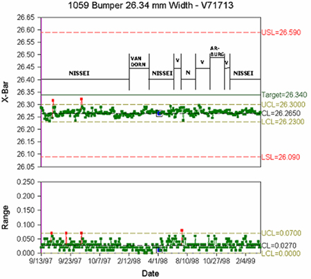
Let’s look at an actual example of dimensional data from a production process. The data shown below was taken from a mold run on three machines where the in-cavity template was matched at each setup. This particular job was run, monitored, and controlled over a two-year period. Figure 2 shows the dimensional data taken from SPC checks throughout the run. Both the X-Bar (average measurement) and Range (process variation) remain identical, regardless of machine.
In summary, the use of in-cavity data allows identical parts to be molded on a wide variety of machines, reducing or eliminating the costs of re-qualifying the process each time the mold is moved. The use of process templates will significantly reduce the time it takes to set-up a job in an alternate machine, providing a cost saving to the molder. This technology is not new – it has been used successfully in production environments for over 20 years. This approach can provide a critical advantage to molders looking to reduce costs and improve quality.
Containment of Abnormal Parts Using Cavity Pressure
In today’s global economy absolute quality to the customer is the world standard for any successful molder. While all molders talk about world class Lean Manufacturing and total quality, the fact is that most are still attempting to “sample and sort” their way to total quality with little success.
Is there available technology to allow totally automated quality for injection molded parts?
In this article we will describe the relationship between common reject types and how the use of cavity pressure sensors can be used to detect and contain these abnormal events.
Ask any group of molders whether or not they have sent their customers any bad parts in the past year and the reply is fairly predictable: nervous laughter and an “of course”. When we ask for a list of the most probable causes, the list always looks like this:
- Short Shots
- Flash
- Sinks and Voids
- Dimensional Problems
- Warp
- Gloss Gradient
- Splay
- Specks or other Contaminants
- Off Color
This list would be the same anywhere in the world, usually in the same order of frequency.
In order to gain the ability to detect and contain abnormal parts using cavity pressure technology, we must first have an understanding of each molding defect.
Short Shots:
Most understand what a short shot is but when asked to put a numerical value on it, molders and customers alike have a hard time defining it. When it is defined as 0 or Zero they seem even more confused. We have to go on to explain that the absence of plastic in the part also means that no pressure was developed in the unfilled section of the cavity. Typically a minimum cavity pressure of 3000 PSI or 200MPA is required for properly packed parts. When a short shot is viewed from this perspective, we simply have to detect a 200 MPA change in cavity pressure and sort out the parts to totally eliminate short shots from getting to the customer.

Figure 1 shows machine Hydraulic Pressure and End of Cavity Pressure overlaid over several shots showing variation, resulting in short shots.
Flash:
With short shots defined numerically it is easier to define a flashed part made in a properly clamped, undamaged mold. It is an excess of plastic pressure, which deflects the mold open enough to allow the plastic to flash over the cavity parting line. Flash and excess packing often results in parts sticking in the mold with resultant mold damage. If a mold is never allowed to flash or parts to stick due to over packing, flash will be eliminated. Setting upper cavity pressure alarms and sorting parts will eliminate flashed parts from getting into the Good Part box.
Sinks and Voids:
Sinks and voids are both a result of localized under-packing of the cavity and/or a lack of gate seal. All of this shows up as a change in the cavity pressure in the area of the problem. A cavity pressure sensor strategically placed will exhibit the problem.
Dimensional Variations:
As plastic is packed into the cavity after the mold is full it is compressed between 3/4 and 1% per 100 MPA. If the effective cavity pressure across a critical dimensional area of a part changes 100 MPA, the dimensional area will vary around 1%. Crystalline materials may vary even more, especially if cooling varies. If cooling does vary, the shape of the curve will vary during cooling, which can be detected by software. This allows parts to be contained. Dimensional variations in parts can be detected by monitoring the cavity pressure curve shapes and gradients from the gate end of the parts to the end of the cavities. If this pressure gradient is maintained over time part dimensions will be maintained.
Warp:
Warp is non-uniform part distortion as opposed to shrinkage variation overall. Changes in warp are caused by changes in packing, cooling rate and cooling time. All of these show up in the cavity pressure waveform. Cooling can also be monitored by monitoring coolant temperatures and pressure drop across mold manifolds in order to detect plugged water lines, changes in water flow and incorrect temperature settings.
Gloss gradient:
Many times on cosmetic parts, a variation in gloss is evident. This often occurs from the gate area toward the end of the cavity. Gloss gradients often relate to the rate and amount that the part is packed. Controlling the rate of packing and thus the shape of the cavity pressure curve allows gloss gradients to be eliminated or made consistent.
The remaining defects on the list: Splay, Specks/Contamination, and Off Color issues may not be detectable by cavity pressure data. A small black spec, for example, or a slight color difference typically will not affect the in-cavity conditions. These problems can be very difficult to detect and are usually tied directly to the material itself or other pre-process issues.
Containment:
Armed with the knowledge above it is simple to devise a strategy for abnormal part containment. With real time data from inside the mold cavity for pressures, times, time to pack, integral values, etc, alarm limits can be set to detect most all part defects.
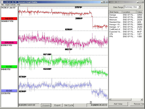
Figure 2 shows summary data values with alarms set for detection and containment.
If an alarm condition is detected, a signal is sent from the eDART System™ to some means of automatically containing the abnormal parts. Robots, reversing conveyors, and flipper chutes are commonly used, but any device that can accept an input signal and divert the parts to a “suspect” location may be utilized. This strategy of using cavity pressure sensors to contain abnormal parts opens the door for molding companies to provide total quality to the customer and eliminates the winless battle of trying to sort to today’s expected quality levels.
Troubleshooting Processes Using Cavity Pressure Sensors
Troubleshooting can take on many meanings for injection molders. All too often they find themselves running to a machine, turning knobs and pushing buttons, hoping with fingers crossed that the next parts out of the mold will be better than the last. Obviously, this practice typically results in wasted production time and escalated material costs and usually doesn’t address the root cause of the real problem. It is very easy to fall into a trap of making multiple adjustments that are not truly related to the problem to be solved, stacking more problems on top of the original problem. Short-term improvements to part quality will often times only mask the actual issue.
Most molders would agree that before any effective troubleshooting can take place, one must first determine what changed in the process. The ability to determine what changed to cause the problem at hand relies on the quality of data available. If the troubleshooter has access to accurate data related to the original or target process, shooting or better yet, killing the trouble can be simple. The key is having that crucial information available so when shots are fired, the trouble is killed and not just wounded from sporadic shooting. Trouble that is merely shot but not killed, is guaranteed to return.
In past articles of this Cavity Pressure Series, we’ve discussed utilizing data from cavity pressure sensors to create an electronic template or blueprint of the process. This template is a representation of the desired cycle from data captured inside the mold cavity where the parts are being molded. We’ve discussed using templates and cavity pressure data to create machine and location independent molding operations. This strategy allows the mold to be moved to another machine or to a totally different facility and the cavity pressure template matched, producing the same parts regardless of geography.
As we discussed last month, containment strategies using cavity pressure technology allow the molder to immediately contain any suspect parts based on in-cavity conditions. The same events that cause suspect parts to be contained, also illustrate process variations that can significantly streamline Troublekilling practices. When process variation occurs that will affect part quality, the graphical profiles or curves from the cavity pressure sensor(s) will clearly show changes happening inside the mold.
The two types of data that any high quality data acquisition system such as the eDART System™ should provide are: a picture of each molding cycle in real time and data over time to detect and display trends. Both types of cavity pressure information prove priceless to the troubleshooter. The real time cycle data is plotted over time as the part is being molded. With the template visible, the current cycle curves overlay the template. Any variations in the cavity pressure profiles are immediately evident as a variance from the template curves.

Figure 1 shows a Cycle Graph with a Template and the current cycle drawn on top.
Defects such as dimensions, flash, shorts, and part weight are directly correlated to the total volume of plastic delivered to the mold cavity, which is directly correlated to the amount of cavity pressure in the cavity. If the cavity pressure curve reaches a peak that is lower than the template or ideal cycle, there was less plastic delivered. If the peak cavity pressure climbs higher than the template peak, this would indicate more plastic being packed into the cavity. Troublekilling dimensional inconsistencies may require recording data over time and correlating trends in cavity pressure data to specific cycles or to specific parts. All the cavity pressure data is saved to a file that can be replayed for evaluation. Specific production runs or even single cycles can be retrieved by recalling the date and time of the cycles to be analyzed. This ability to go back in time and analyze cavity pressure information is very crucial since some molding defects may not come to light immediately.
Cosmetic concerns such as gloss level and texture level are related to the rate of packing. The slope of the cavity pressure curve during pack (pressure rise over time) illustrates the pack rate. If the cavity pressure curves reach their peak sooner or later that the template, a variation in gloss or texture may result.
If there is a cavity pressure sensor located near the gate area inside the cavity, it can be utilized to determine if the gate is sealed. If the gate is not sealed at the time that the holding pressure is released, plastic will discharge from the cavity back into the runner. The gate end cavity pressure curve will suddenly drop concurrent with the end of holding time. Figure 2 shows two cycles overlaid on each other. One showing gate seal and the other shows discharge.
Thermal variations such as heater band cycles or hot runner heater cycles will many times show up on cavity pressure data. This type of variation may be subtle and require more data to detect. Thermal cycles will typically be repeating cycles within the data. For example, as the hot runner heaters cycle on and off, the viscosity of the material is affected. Hotter plastic will have somewhat less resistance to flow and therefore render a higher peak cavity pressure. So the peak cavity pressure will trend up and back down with repeatable frequency from thermal cycling.
By now the benefits of having cavity pressure data are clear. Data from inside the cavity is the only data that can clearly and without doubt open a window for the molder to view all aspects of the molded part being created. Troublekilling is obviously streamlined by the ability to “see” what is happening inside the cavity. With the lights on in the cavity, any changes to the ideal conditions in the mold will be illuminated.
Revalidation Using Machine Independent Data
Submitted by:
Rod Groleau, Chairman & CEO
Patricia Hirst, Marketing Coordinator
RJG Inc, Traverse City, MI
As the injection molding industry continues to evolve in the face of issues such as globalization, downsizing and short run quotas, customer demands are increasing for both the mold builder and molder. More and more companies are going off shore for the production of molded components and assemblies. Mold builders and molders alike are looking for ways to streamline their processes and decrease turn around time in order to meet the demands of their customers.
Molders are facing increased demands for shorter lead times and more stringent quality requirements from their customers. For the sake of survival, they need to find progressive mold builders that have invested in technologies and strategies to help them meet today’s challenges. They are looking for ways to reduce or eliminate costly start-up runs that are time consuming and eat into the profits of the job. Optimally they are looking for mold builders that can supply Ready-To-Go-Molds that have already been put through rigorous paces and arrive at the molders door complete with a template that the molder can easily match on the production floor. What is a Ready-To-Go mold? It starts with a good mold design, which is cut properly, assembled properly, with balanced cavities, and checks must be made to ensure that all items function as designed, clearances are proper and water lines are correct based on flow. Last but not least the mold must be challenged with a rigorous mold tryout, leaving no stone unturned. The mold builder must validate mold performance requirements prior to delivery of the mold. Today, molds need to arrive at the molders door with a guarantee that the first part produced will be good, not 2, 3 or 10 shots down the line.
Molders can no longer afford to spend the better part of a day setting up a job and developing a process. They are looking for ways to streamline the initial process set-up, as well as the time it takes to repeat the set-up process when a mold is moved to another machine. In addition, many molders are required to provide data or proof that the parts they are supplying are of the highest quality. If a molding job is transferred to a new machine they are being asked to provide documentation proving that the process has not been compromised by the move. Anyone that runs a molding facility knows that moving molds from one machine to another or one facility to another as scheduling allows, is inevitable. The ability to quickly move molds from one machine to another or from one facility to another, without an abundance of downtime, is an invaluable advantage.
In summary, to remain a key competitor, companies must adapt to the new demands of the market and restructure their way of doing business to become more efficient at what they do. The best way to accomplish this may be for them to walk a mile in their customer’s shoes. Remember that technology never comes looking for you, but it sure can pass you by.
RJG, Inc. is a supplier of in-mold cavity pressure sensors, cavity pressure control equipment and systematic processing training. In addition they offer a certification program for mold builders and tooling engineers. For more information visit their web site at www.rjginc.com.
